Awesome work Gerry !! :heat: :good: This would make a great tutorial on how to bring the early wings wiring further up to par with the needs of today with the use of relays and the separation of the systems. :laptop: Do you think that a wiring diagram might be available in the not to distant future ? :whip: Hint-Hint :beg: :beg: :whistling: :whistling: :hihihi:
You are using an out of date browser. It may not display this or other websites correctly.
You should upgrade or use an alternative browser.
You should upgrade or use an alternative browser.
Rebuild '82 Standard Wire Harness and Fuse Box
- Thread starter mcgovern61
- Start date


Help Support Classic Goldwings:
This site may earn a commission from merchant affiliate
links, including eBay, Amazon, and others.
OP
OP
- Joined
- Dec 3, 2009
- Messages
- 10,961
- Reaction score
- 228
- Location
- Kingsport, Tennessee
- My Bike Models
- Former '82 GL1100 "The Slug"
Once I have everything planned to my satisfaction and then tested, I will create a one line diagram of the system changes.
Super !! You da man !!
OP
OP
- Joined
- Dec 3, 2009
- Messages
- 10,961
- Reaction score
- 228
- Location
- Kingsport, Tennessee
- My Bike Models
- Former '82 GL1100 "The Slug"
Speaking of wiring diagrams and one line schematics, I have followed the '82 Standard and '83 Standard color schematics in the gallery plus following all of the wires in the old '82 harness and I am surprised at how many circuits do not have fuses.
The fan and ignition (including the coils and igniters) all run directly from the positive wire that comes from the 30 amp fuse to the key switch and back. No other fuses for them except the 30 amp fuse at the battery.
My next step is determining how many new connectors I need to make connections from the fuse panel to the original wires and to run a new harness section up to the new buss bars. I like the connectors used in the 1200 wiring. The spades are much bigger than in the 1100 connectors. BUT, I cannot find them anywhere. The watertight connector types are bit expensive by the time you add them all up. Looks like I am heading back to Vintage Connections to get the original type.
Pretty sure the 9 pin at the reg/rec is 6.3 mm spade as is the starter solenoid 4 pin. I haven't measured the other ones yet but think they are the 2.8 mm. I'm going to stick with the OEM style that I have on order from vintage now and count on the dialectic grease to do its job and not bother with waterproof connectors. I see what you mean about non fused circuits. I think vintage has the size spades needed if I'm looking right
- Joined
- Jan 27, 2013
- Messages
- 9,855
- Reaction score
- 34
- Location
- Brisbane Australia
- My Bike Models
- 1981 GL1100 “Rats Nest”
1998 GL1500c Val
1987 CBR1000f “The Pig”
1991 CBR1000f Red
+1 on the normal FM type plugs. :good:
OP
OP
- Joined
- Dec 3, 2009
- Messages
- 10,961
- Reaction score
- 228
- Location
- Kingsport, Tennessee
- My Bike Models
- Former '82 GL1100 "The Slug"
It looks like Vintage has the M63/F63 for 14-18 gauge wire. They are the right connectors for what I am doing! :yes:[url=https://classicgoldwings.com/forum/viewtopic.php?p=182313#p182313:2rxw7idh said:backlander » Sat Oct 15, 2016 4:57 am[/url]":2rxw7idh]
Pretty sure the 9 pin at the reg/rec is 6.3 mm spade as is the starter solenoid 4 pin. I haven't measured the other ones yet but think they are the 2.8 mm. I'm going to stick with the OEM style that I have on order from vintage now and count on the dialectic grease to do its job and not bother with waterproof connectors. I see what you mean about non fused circuits. I think vintage has the size spades needed if I'm looking right
OP
OP
- Joined
- Dec 3, 2009
- Messages
- 10,961
- Reaction score
- 228
- Location
- Kingsport, Tennessee
- My Bike Models
- Former '82 GL1100 "The Slug"
While taking a holiday break from this project, I was looking at the wiring on the bike and with my AGM battery starting to lose power I see that the headlight really pulls a lot out of the battery when the key is turned on. Since the new system will have a relay for the headlight, I am thinking of putting the relay trigger on a normally open oil pressure switch. That way, when the engine is off, the light goes off. We use these switches in marine all the time to turn systems on and off.
- Joined
- Jan 27, 2013
- Messages
- 9,855
- Reaction score
- 34
- Location
- Brisbane Australia
- My Bike Models
- 1981 GL1100 “Rats Nest”
1998 GL1500c Val
1987 CBR1000f “The Pig”
1991 CBR1000f Red
One thing I like about my early Australian delivered CBRs is the ability to turn off the headlight when short on power and just use the park light circuit. There are some tachometric relays out there that use the tacho/coil output to close the relay contacts which are used in electric fuel pump and some motorcycle headlight circuits.
- Joined
- Jun 9, 2012
- Messages
- 1,053
- Reaction score
- 3
- Location
- Centralia Illinois
- My Bike Models
- 1984 GL1200I
1988 GL1500
[url=https://classicgoldwings.com/forum/viewtopic.php?p=185148#p185148:5ixo6kj1 said:mcgovern61 » Wed Dec 21, 2016 2:51 pm[/url]":5ixo6kj1]
While taking a holiday break from this project, I was looking at the wiring on the bike and with my AGM battery starting to lose power I see that the headlight really pulls a lot out of the battery when the key is turned on. Since the new system will have a relay for the headlight, I am thinking of putting the relay trigger on a normally open oil pressure switch. That way, when the engine is off, the light goes off. We use these switches in marine all the time to turn systems on and off.
This is a great idea! I'm going to steal it and apply to my bikes. This will allow full voltage to the ignition system during startup.
You could also use this to cut the ignition off if you had no oil pressure.
OP
OP
- Joined
- Dec 3, 2009
- Messages
- 10,961
- Reaction score
- 228
- Location
- Kingsport, Tennessee
- My Bike Models
- Former '82 GL1100 "The Slug"
This poor project is still on standby mode. Since the Holiday's and getting the other 1100, this old girl has been moved outside with a cover over her to make room to work on the '81 1100. My goal is to start this project up again by March. We should have the '81 clean and running by then if not sooner and then move this girl back in. :wave:
OP
OP
- Joined
- Dec 3, 2009
- Messages
- 10,961
- Reaction score
- 228
- Location
- Kingsport, Tennessee
- My Bike Models
- Former '82 GL1100 "The Slug"
Remember this old set of coils from my '82 with the bad wires and resistor?
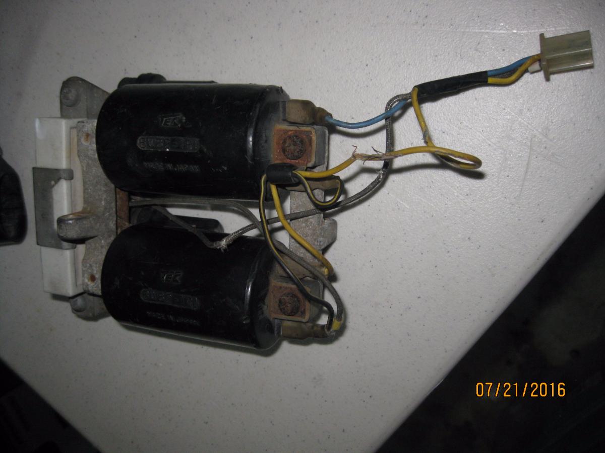
Look what showed up on Ebay for $17:
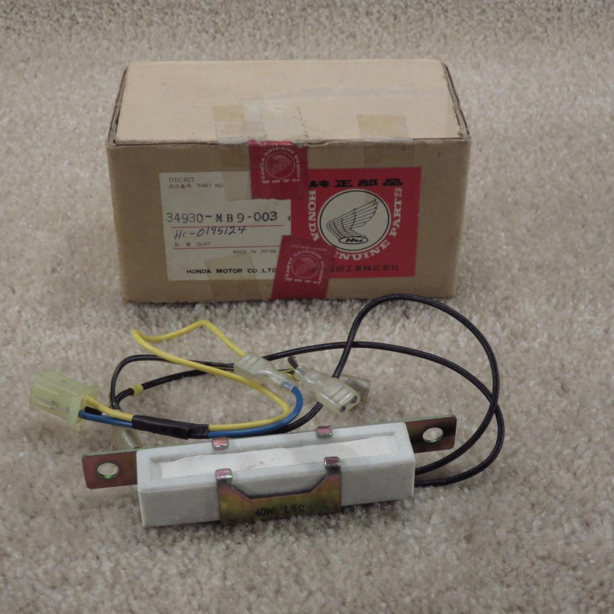
 arty: :yahoo: :Egyptian:
Look what showed up on Ebay for $17:
arty: :yahoo: :Egyptian:- Joined
- Dec 3, 2009
- Messages
- 22,402
- Reaction score
- 237
- Location
- Van Nuys Ca.
- My Bike Models
- 1983 Interstate
2018 KLR 650
2018 BMW S1000 RR
- My Bike Logs forum link
- https://classicgoldwings.com/forums/dan-filipi.122/
Nice. Grab it!
OP
OP
- Joined
- Dec 3, 2009
- Messages
- 10,961
- Reaction score
- 228
- Location
- Kingsport, Tennessee
- My Bike Models
- Former '82 GL1100 "The Slug"
Yep, already on the way!! :yahoo:[url=https://classicgoldwings.com/forum/viewtopic.php?p=186568#p186568:3q0gbv36 said:dan filipi » Wed Feb 01, 2017 3:33 pm[/url]":3q0gbv36]
Nice. Grab it!
OP
OP
- Joined
- Dec 3, 2009
- Messages
- 10,961
- Reaction score
- 228
- Location
- Kingsport, Tennessee
- My Bike Models
- Former '82 GL1100 "The Slug"
Pushing the '81 out of the way and setup the table with the wire harness again and it is like learning the whole fuse panel and relays all over again. :head bang:
Good thing I took copious notes and made lots of diagrams back then! :heat:
I am still thinking through the new connectors for the fuse/relay panel. The Vintage connectors are cheap enough, but those Deutsch connectors are pretty nice. :lust:
Two 12 pin and one 3 pin connector set would do it. The issue is that I would have to buy their crimping tool or I cannot use those connectors. $50 for the tool with one connector! :shock:
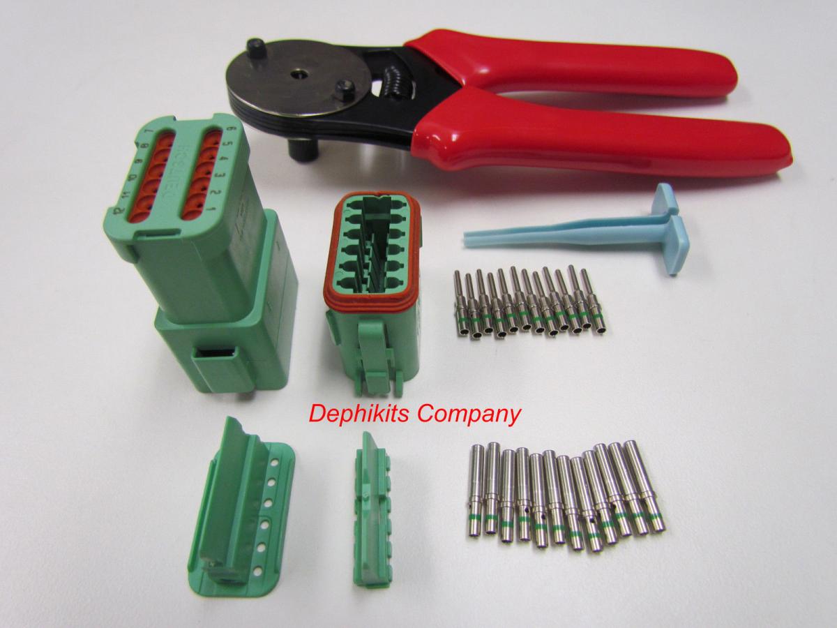
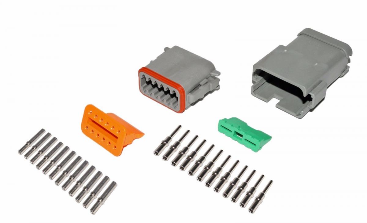
But they sure would look nice (and watertight). Thinkin........thinkin............
Good thing I took copious notes and made lots of diagrams back then! :heat:
I am still thinking through the new connectors for the fuse/relay panel. The Vintage connectors are cheap enough, but those Deutsch connectors are pretty nice. :lust:
Two 12 pin and one 3 pin connector set would do it. The issue is that I would have to buy their crimping tool or I cannot use those connectors. $50 for the tool with one connector! :shock:
But they sure would look nice (and watertight). Thinkin........thinkin............
slabghost
Well-known member
To the next guy you'll be the crazy PO that installed all the strange stuff on the wiring. Better plan on attaching a copy of all your notes to the sale if you ever sell it.
OP
OP
- Joined
- Dec 3, 2009
- Messages
- 10,961
- Reaction score
- 228
- Location
- Kingsport, Tennessee
- My Bike Models
- Former '82 GL1100 "The Slug"
For sure! :smilie_happy:
I will be making a one line drawing of the entire harness before installation. I could even do it in AutoCAD to make it look real professional.
I will be making a one line drawing of the entire harness before installation. I could even do it in AutoCAD to make it look real professional.
OP
OP
- Joined
- Dec 3, 2009
- Messages
- 10,961
- Reaction score
- 228
- Location
- Kingsport, Tennessee
- My Bike Models
- Former '82 GL1100 "The Slug"
Back at it again. I got a chance to connect the fuse/relay panel to the buss bars and I ran power from my battery to the two circuits to test. I used the 12 volt router power supply to fire the relays and everything works exactly as planned! :yahoo:
I was going to move my Stebel Nautilus horn circuit to relay #2 in the fuse panel, but I came across a minor issue. The horn came with an installation kit back in '07 that is wired directly to the battery with 14 gauge wire, a 30 amp inline blade fuse and relay. I got a little bit concerned that it came with a 30 amp fuse! :shock:
I thought I had better check the amperage draw while the horn (really the compressor) is in operation. I have an alternator ammeter tool to test current flow that is good to 80 amps. Just drop it onto the wire and draw some juice. It is a very sensitive device. I setup on the power wire coming directly from the battery and blew the horn for 6 seconds or so. To my surprise, that compressor had a constant 22-25 amp draw on the battery! :shock:
Maybe I will leave it hooked as is right on the battery? :BigGrin:
slabghost
Well-known member
Good idea. Or ditch it. I haven't used my horn in over a year.
OP
OP
- Joined
- Dec 3, 2009
- Messages
- 10,961
- Reaction score
- 228
- Location
- Kingsport, Tennessee
- My Bike Models
- Former '82 GL1100 "The Slug"
Not around here. Traffic is real close together and there are way too many close calls with people texting and driving. In the course of a 50 mile ride around here, I might have to hit the horn at least twice because of distracted drivers heading into my lane. Many of these same drivers think turn signals are optional and that lane drifting is an acceptable method for driving. :rant:[url=https://classicgoldwings.com/forum/viewtopic.php?p=190294#p190294:2wsa2osq said:slabghost » Sun May 07, 2017 9:09 pm[/url]":2wsa2osq]
Good idea. Or ditch it. I haven't used my horn in over a year.