OP
OP
When I started to work on my ’85 Limited Edition back in 2016, I had a steep learning curve and made a lot of mistakes. Nothing catastrophic, but enough to screw up the OEM settings, one being how to adjust the TPS.
Have been adjusting the throttle position sensor (TPI) as it has a significant impact on what the ECU does on start and during operation. As with all learning curves, I thought that the TPS was the root cause for any fuelling issue the engine had.
Not a lot written about this except in the Supplement, and if not read and understood, can lead you down the proverbial rabbit hole - BTDT.
The Supplement has information on the TPS voltage calibration, 0.475 to 0.495 VDC, and you are not to adjust the throttle body lever stop screw. This is most important because the throttle body lever stop screw is set at the factory, and the setting of this screw is black magic, a black art so to speak.
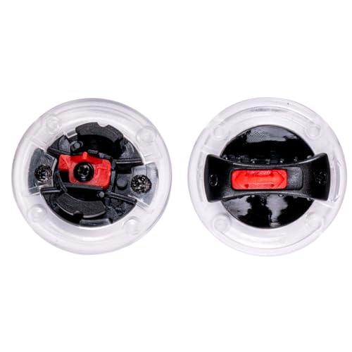
These pictures show the throttle body lever, stop screw and the feeler gauge used:


The procedure to adjust the TPS is to bring the throttle body lever to the throttle body lever stop screw by backing off on the engine idle screw until the throttle plates are completely closed and there is no tension on the engine idle adjusting screw. As mentioned do not adjust the throttle body lever stop screw. The throttle body lever is only in place for the adjustment of the TPS.
When you back off the engine idle adjusting screw, count the number of turns so that you can duplicate and return the engine idle adjusting screws to the same position before starting.
Providing you can rotate and adjust the installed TPS, rotate it counter-clockwise, or clockwise as required to get a TPS voltage of 0.475 to 0.495 VDC. Tighten the screws, TPS value may change, and needs to be verified when tightened.
Take out the 0.110” feeler gauge, and reset the engine idle screw.
When this is done, check the TPS calibration. It should be the same voltage as when you calibrated the TPS with the feeler gauge. This is why the OEM mentions in the calibration procedure to not adjust the throttle body lever stop screw. May take you a few hours of calibrate then test to get the throttle body stop screw properly set if you move it.
This is important to understand. The setting of the throttle body lever stop screw, the calibration voltage, and the engine idle screw position are interrelated.
The voltage of 0.475 to 0.495 VDC is the voltage signal that the ECU uses to determine the position of the throttle plate(s) on engine start. Indicates that the throttle plates are in the closed throttle (CT) position.
I had thought that using the TPS you could impact on the injector fuelling profile. This may be possible/probable, but the impact of the TPS calibration is for the TPS signal to indicate that the throttle plates are closed, and with all electronic components, there is generally a range, be it small in this case, that is used.
You can check for wide open throttle (WOT) position by turning the throttle to the full open position and you should get approximately 4.5 VDC, may not. Mine is at 3.95 VDC. The important number is for the closed throttle position.
If there is a fuelling issue with the ’85/’86 FI models, it will probably be because one or more calibration settings are not in the required range(s).
The throttle plates on the ’85/’86 FI models are closed when the engine is at idle, or on deceleration. This is different from the carb models where the throttle plates are never fully closed.
When the computerized fuel system came into being with the 1982 CX500 Turbo and 1983 CX650 Turbo motorcycles, Honda realized that at idle and on deceleration the engines were being starved for combustion air.
To compensate for this the Idle Air Control (IAC) system came into being. This is a passive air system that provides air to the cylinders on engine start, and engine deceleration.
The Reed valves inject air into the cylinders on the downside of the throttle plates to keep the engine operating at idle. The effectiveness of the IAC system can be checked by removing the air hose from the air chamber to the IAC valve and putting your finger over the IAC valve inlet. The engine will stall.
It incorporates reed valves, operated by engine vacuum, and an IAC valve that is connected to the air chamber for combustion air.
The IAC valve opens and closes (never fully closed) by using a bimetal strip that when cold, has the IAC valve in the fully open position. It is connected to a DC power source and when the IAC valve bimetallic strip heats up it moves an internal component, partially closing the air inlet aperture. This IAC valve air inlet aperture is fully open on a cold start to provide sufficient air into the engine cylinders for proper fuel combustion at fast idle.
Have been adjusting the throttle position sensor (TPI) as it has a significant impact on what the ECU does on start and during operation. As with all learning curves, I thought that the TPS was the root cause for any fuelling issue the engine had.
Not a lot written about this except in the Supplement, and if not read and understood, can lead you down the proverbial rabbit hole - BTDT.
The Supplement has information on the TPS voltage calibration, 0.475 to 0.495 VDC, and you are not to adjust the throttle body lever stop screw. This is most important because the throttle body lever stop screw is set at the factory, and the setting of this screw is black magic, a black art so to speak.
These pictures show the throttle body lever, stop screw and the feeler gauge used:


The procedure to adjust the TPS is to bring the throttle body lever to the throttle body lever stop screw by backing off on the engine idle screw until the throttle plates are completely closed and there is no tension on the engine idle adjusting screw. As mentioned do not adjust the throttle body lever stop screw. The throttle body lever is only in place for the adjustment of the TPS.
When you back off the engine idle adjusting screw, count the number of turns so that you can duplicate and return the engine idle adjusting screws to the same position before starting.
Providing you can rotate and adjust the installed TPS, rotate it counter-clockwise, or clockwise as required to get a TPS voltage of 0.475 to 0.495 VDC. Tighten the screws, TPS value may change, and needs to be verified when tightened.
Take out the 0.110” feeler gauge, and reset the engine idle screw.
When this is done, check the TPS calibration. It should be the same voltage as when you calibrated the TPS with the feeler gauge. This is why the OEM mentions in the calibration procedure to not adjust the throttle body lever stop screw. May take you a few hours of calibrate then test to get the throttle body stop screw properly set if you move it.
This is important to understand. The setting of the throttle body lever stop screw, the calibration voltage, and the engine idle screw position are interrelated.
The voltage of 0.475 to 0.495 VDC is the voltage signal that the ECU uses to determine the position of the throttle plate(s) on engine start. Indicates that the throttle plates are in the closed throttle (CT) position.
I had thought that using the TPS you could impact on the injector fuelling profile. This may be possible/probable, but the impact of the TPS calibration is for the TPS signal to indicate that the throttle plates are closed, and with all electronic components, there is generally a range, be it small in this case, that is used.
You can check for wide open throttle (WOT) position by turning the throttle to the full open position and you should get approximately 4.5 VDC, may not. Mine is at 3.95 VDC. The important number is for the closed throttle position.
If there is a fuelling issue with the ’85/’86 FI models, it will probably be because one or more calibration settings are not in the required range(s).
The throttle plates on the ’85/’86 FI models are closed when the engine is at idle, or on deceleration. This is different from the carb models where the throttle plates are never fully closed.
When the computerized fuel system came into being with the 1982 CX500 Turbo and 1983 CX650 Turbo motorcycles, Honda realized that at idle and on deceleration the engines were being starved for combustion air.
To compensate for this the Idle Air Control (IAC) system came into being. This is a passive air system that provides air to the cylinders on engine start, and engine deceleration.
The Reed valves inject air into the cylinders on the downside of the throttle plates to keep the engine operating at idle. The effectiveness of the IAC system can be checked by removing the air hose from the air chamber to the IAC valve and putting your finger over the IAC valve inlet. The engine will stall.
It incorporates reed valves, operated by engine vacuum, and an IAC valve that is connected to the air chamber for combustion air.
The IAC valve opens and closes (never fully closed) by using a bimetal strip that when cold, has the IAC valve in the fully open position. It is connected to a DC power source and when the IAC valve bimetallic strip heats up it moves an internal component, partially closing the air inlet aperture. This IAC valve air inlet aperture is fully open on a cold start to provide sufficient air into the engine cylinders for proper fuel combustion at fast idle.