I have a 1983 Honda GL1100 Aspencade. The other day while riding it, the temperature gauge went almost to the red, yet the engine was not overheating.
I parked the bike on Thursday night. When I put the key in to start it Friday evening, the temperature gauge was half way between cold and hot, yet the engine had not been run in nearly 20 hours.
I started it up and rode about 35 miles, and once again the temperature gauge went to the last LCD segment before the red. But still was not overheated.
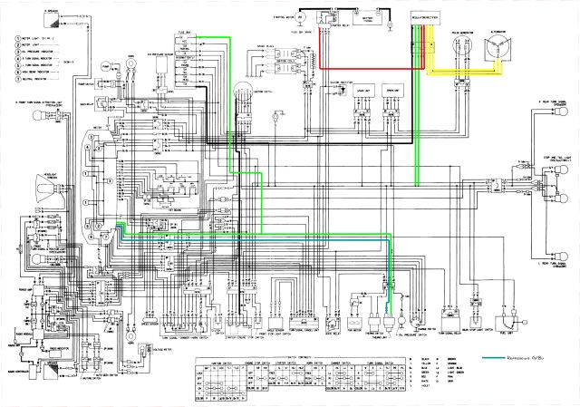
Does anyone have any ideas as to where to begin looking; sending unit, wiring, digital gauge,...? Is there a way to test the sending unit? How about the gauge?
The sending unit is part number 37510-MB9-871 and is no longer available from Honda. I have located a brand new one, but due to the cost, I would like to diagnose and test the system because the sending unit is far from cheap.
Any help would be greatly appreciated!
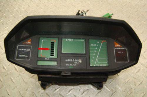
The red arrow in the image below indicates where the gauge shows when the engine is cold. After warming up, it runs up to the last segment before the red 'HOT' mark.
Thank you! :thanks:


