Idler pulley rebuild or buy new?

Classic Goldwings

Help Support Classic Goldwings:

This site may earn a commission from merchant affiliate links, including eBay, Amazon, and others.
Dan...can ya get a pic of the backside of that thing? You can prolly press the whole thing out from the back....stud and all. Just thinkin out loud here. :headscratch:
 
[url=https://www.classicgoldwings.com/forum/viewtopic.php?p=124484#p124484:2ca6990i said:
AApple » Mon Jul 07, 2014 9:46 am[/url]":2ca6990i]
Dan...can ya get a pic of the backside of that thing? You can prolly press the whole thing out from the back....stud and all. Just thinkin out loud here. :headscratch:
If you save that picture to your computer then print it on double sided paper, you can flip it over to see the other side.
 
[url=https://www.classicgoldwings.com/forum/viewtopic.php?p=124486#p124486:1mzaiwof said:
dan filipi » Mon Jul 07, 2014 9:55 am[/url]":1mzaiwof]
[url=https://www.classicgoldwings.com/forum/viewtopic.php?p=124484#p124484:1mzaiwof said:
AApple » Mon Jul 07, 2014 9:46 am[/url]":1mzaiwof]
Dan...can ya get a pic of the backside of that thing? You can prolly press the whole thing out from the back....stud and all. Just thinkin out loud here. :headscratch:
If you save that picture to your computer then print it on double sided paper, you can flip it over to see the other side.
Cool!! 3-D printing on the cheap! :hihihi:
 
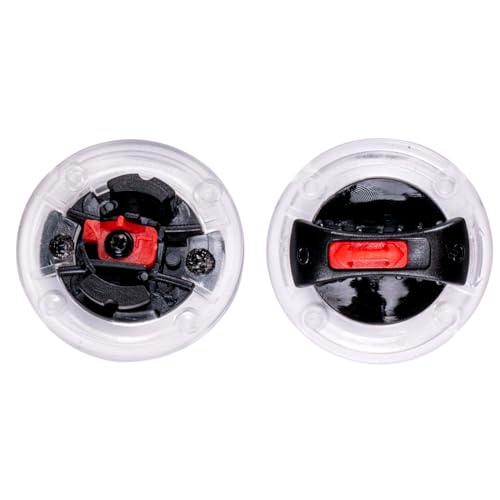
Idler plates back side.
image.php
 
I fixed these up by drilling out like you did, turning a couple bolts down on the lathe, and mounting the Gates T42015 bearings I bought on Amazon. There are instructions (somewhere) on the 'net.
a5a6y3y2.jpg

Bought the bolts at the local Ace hardware. The heads of the bolts are cut down in the lathe for no interference. The nuts are self-locking.
 

Attachments

  • uploadfromtaptalk1404778776137.jpg
    uploadfromtaptalk1404778776137.jpg
    36.2 KB
Thanks pidjones.

One pulley is done.
This is how I did it.

Thanks out to sandiegobrass for laying this out most of the way.
I did a couple things differently but his research and tutorial helps a bunch!

I drilled the back side of the pulley to 1/2" which wasn't quite enough to let the pulley break loose of the plate.
I put the assembly across the jaws of the vise and hit it but there was still too much metal left to let go.
The back plate bent a bit:

image.php


So I went a little further using this Dremel tip in the drill press. A larger drill bit would work too but this is what I have:
image.php


image.php


That much let it break loose:
image.php


Plate on the flat concrete floor and hammer it flat.

This is the Gates # T42015 pulley going on:
image.php


Using this 3/8"x1" carriage bolt, lock washer and nut:
image.php


Back side of the carriage bolt through the plate:
image.php


The front side.
3/8" is smaller than the hole but the carriage bolt square part holds it very close to center:
image.php


I tack welded the carriage head on the back side to hold it from turning when tightening the bolt later.
Tack it on the sides so the welds don't interfere with the engine block when installing:
image.php


Plate support tab on the block seen below the bracket:
image.php


Test fit:
image.php


Assembled and installed.
I'll take it apart and use red loc-tite.
image.php


image.php


[video]https://youtu.be/RjWIXEaZkmU[/video]
 
Just FYI,
I had read of one guy saying this Gates idler started making noise in 1000 miles and that there was no grease in it so I checked these 2. Easy to do.

Get a tiny flat screw driver at the edge and work it upward:
image.php


image.php


Both mine had plenty of grease:
image.php


When your done looking or putting more grease in it, use whatever flat tool ya have handy to push the seal back in all around it:
image.php


The seal on both sides of the bearing come off and go back on the same way.
 
Nice job Dan! The only possible query I have is with the carriage bolt and the tensile strength of it, over here they can be very low grade and can be quite soft. That being said I have seen them stretch rather than shear due to the lower tensile strength so I guess only time will tell. Wheel studs that have been used by others are grade 8 or better.
 
[url=https://www.classicgoldwings.com/forum/viewtopic.php?p=124568#p124568:1pvhtc28 said:
Ansimp » Mon Jul 07, 2014 6:28 pm[/url]":1pvhtc28]
Nice job Dan! The only possible query I have is with the carriage bolt and the tensile strength of it, over here they can be very low grade and can be quite soft. That being said I have seen them stretch rather than shear due to the lower tensile strength so I guess only time will tell. Wheel studs that have been used by others are grade 8 or better.
I completely agree but not in the 3/8".
I've had 5/16" and especially 1/4" snap.
For that matter I've had hardened wheel studs snap right off.
 
[url=https://www.classicgoldwings.com/forum/viewtopic.php?p=124573#p124573:33as4scl said:
Steve83 » Mon Jul 07, 2014 7:07 pm[/url]":33as4scl]
There's not much tension on these bolts and bearings, since they're not on the pull side of the belt. High speed, heat, and age is what kills these.
Agreed. And if there were a lot of tension on them the aluminum standoffs holding the plate to the block would be snapping off.
 
Looks like what I did may be for naught anyhow and I need to come up with a solution.

Once the 1100 idler and pulley are bolted on, the bolt head hits the aluminum back support piece which allows no belt adjustment. Well belt is too tight. It's worse using a 1200 idler plate.
Hmm. I might have to grind the bolt head off some.
Don't want to modify that support tab.
 
Nice job, Dan. I will follow the same path, maybe use the wheel studs if they can be found small enough. I think others had to grind them flat on the back.
 

Latest posts

Top