1985 GL1200 Limited ECU Replacement/Upgrade - Part 2

Classic Goldwings

Help Support Classic Goldwings:

This site may earn a commission from merchant affiliate links, including eBay, Amazon, and others.
Took the starter in to the local electrical shop this morning, estimate and have back in hand same day. Asked about the rebuild, worn out. The fellow that did the work mentioned that this starter is a one of for the Limited Edition, parts search. Cost was less than a replacement, and done same day as mentioned.

Will install tomorrow and continue with the project.

Will be putting the '84 starter up for grabs, pay the shipping. Going to start another house cleaning to find a new home(s) for the items I have been collecting.
 
Update on project.

It's definitely testing my resolve. Timing and sync losses are at the top of the list, and no matter what I have done to date, I have not been able to hit on the issue(s).

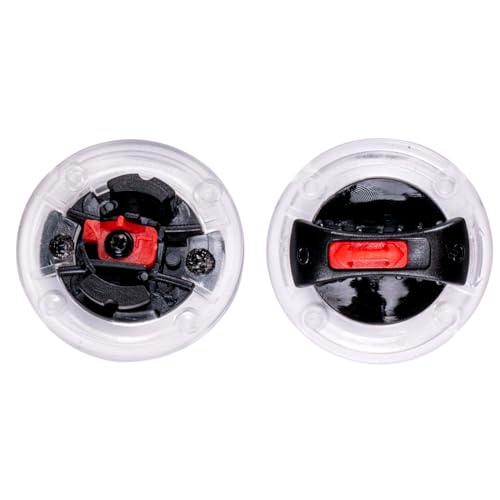
Have learned a bit more about the GR/GL cam sensors and why these are designed this way. Number one - space requirements and secondly, there are two sensors. VR sensor components are:

1 - housing
2 - output wires
4 - permanent magnet
5 - inductive coil
6 - pole pin
VR Sensor Explained.jpeg
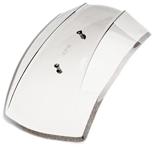
All nicely wrapped in a plastic housing - Ns crank sensor shown:
Ns - Crank Sensor.JPG
The '85/'86 GW FI models use the above Ns crank sensor but it is quite bulky. I have often asked myself about the reason for the magnet and it is now clear. Honda did a three part GR/GL cam sensor for these FI models mainly because of space constraints and the use of two sensors. The housing for the cam sensors is the brushed aluminum cover:
GR-GL sensor 2 - Explained.jpg
Question(s) have been asked if the magnet is important and needs to be there - the answer is yes. The manual requires a specific air gap. This is the gap between the pole pin and the trigger wheel not the inductive coil and the trigger wheel. The manual is not very clear about this.

Back to the update. Have been having issues with wiring, getting it correct and using the OEM wiring to do this. Not too easy a task. Timing is a bigger issue. Have not been able to get it consistent. Time to go back to the beginning and start fresh. Shouldn't be such a difficult task this ECU replacement, but it is.

The software that I use to look at data is MegaLogViewer: This a pic of the captured cam/crank info. The green is the cam sensor, blue is crank. Crank signal is very good, but the cam signal has a loss that is very prominent - the signal loss is related to the cam sensor trigger wheel design. There is the tooth spike when the trigger wheel passes the sensor, the next spike - loss of signal occurs because there is a small dimple after the trigger wheel tooth, then the total loss of signal when the cam trigger wheel design moves far enough away from the sensor. The above picture that shows the parts of the cam sensor with the cam sensor trigger wheel, shows the small dimple after the cam wheel trigger tooth. This is causing the sync loss shown in the pic below. The pic below does show that the cam sensor signal is at #1 cylinder after 16 teeth have passed over the crank - Ns sensor.

Screenshot 2023-01-30 at 12.55.16 PM.png
Thinking about getting rid of the small dimple indent in the cam sensor trigger wheel. Need a product that would emulate the ferrous metal of this wheel, just smooth out the profile, no dip. I do have a spare cam sensor wheel if needs be. Would like a product that I could file away should the need arise. If not, make a new cam sensor trigger wheel. The modified cam trigger wheel could be 1" diameter with a single trigger tooth in the same location as original cam wheel:
Cam Wheel Backside.JPG

I wonder about the cam sensor duration. It does mimic the cam sensor trigger wheel profile, but is quite long approximately 3/4 of a crank rotation. Eight teeth on the crank trigger wheel, so the cam signal lasts for 6 teeth. The next cam pulse is after the crank turns 450 degrees, equivalent to 10 crank trigger wheel teeth. - full engine cycle of 720 degrees.

One of the Speeduino forum members theorized that this small cam sensor signal loss might cause the OEM ECU to generate an error code when the second cam sensor fails. If the ECU sees a cam sensor signal between the pulses shown above (pulse is for a single cam sensor connection), there is no error code generated.

Speeduino forum members have suggested a different trigger wheel. To quote a Speeduino member:"So long as the sensor can "see" it and sends a usable signal, it doesn't much matter the size, shape, symmetry, etc, or even the location. You can find threads here (on the Speeduino forum) where we have used saw-cut slots, drilled holes, pop-rivets, bolt heads and all sorts of other features the sensor could read." Here's a pic of a member made cam sensor trigger wheel:
Screenshot 2023-01-30 at 12.58.34 PM.png

Have been contemplating making a new wiring harness specifically for the Speeduino ECU. I would still be able to revert back to the original configuration in a day. Would rule out signal loss in the OEM wiring harness. Sometimes harder to use existing than to make new.

Some of what I have learned so far. More to follow.
 
Just thinkin'. Would the air gap result in a different output signal that may get rid of the 'dip'. In other words, change the gap to smaller and larger to maybe get a different result?

May not make a hoot......
 
Last edited:
Tried this. No change to the dip. Going to fashion a new cam trigger wheel, do a bench test. I have searched the various forum threads for trigger wheel issues and there are a lot, but mostly these new ECUs need to see a defined signal that its relatively short, not drawn out as the Honda cam trigger wheel does. Thinking the OEM cam trigger wheel may be an issue.

My research on the web also indicates that the trigger wheel tooth should be approximately the same width as the sensor pole pin #6. This pic shows the pole pin #6 approximately the same size as the wheel tooth:
VR Sensor Explained.jpeg

The cam/crank trace in my post above shows the cam signal (green) as a rising signal, the blue is for the crank and is a falling signal. This is because the VR conditioner is an inverting conditioner. There are non-inverting VR conditioners as well. The signals come into the VR Conditioner as an AC sine wave and converted to a digital square wave. This pic shows which is which:
Cam-Crank Signals.jpg
When I do the bench test will be testing the cam sensor both ways.
 
Been thinking about the design of the CFI system, how it is wired, the dual component structure, trigger wheel design(s), sensor profiles and such. I have come to a conclusion that modifying to suit an existing design is probably harder than to start from a new slate, come up with a different approach. Not going to let this bump in the road derail the project.

Honda is not alone in this. An example of this is the design of the cam sensor(s) trigger wheel. The design of the cam sensor wheel is specific to the OEM CFI system, and is not the best for a modern aftermarket ECU.

I will be able to revert, but have to be aware that it may take a day or so. The next owner, not for a while though, will need to be an electrical engineer.
:lol:


Have found a program on the Mac - Freeform. Used it yesterday and today to do a wiring schematic for an interim wire hookup - not the most advanced, but allows me to do a relatively good schematic. Doing continuity checks to ensure the pins are correct. Counted up the wires and there are some 21 wires needed for the new harness. Using the accessory fuse box for power and ground may help as well. Power needs to be from a switched source. This fuse box is grounded directly to the battery, not the bike chassis - maybe a little less noise on the ECU side, perhaps. Will be changing the schematic to reflect the actual install such as using an OEM MAP (PBR) sensor wiring for the O2 sensor.

New/temp wiring schematic:
New Temp Wiring.jpg

The fuel pump relay, coils, and CFI main relay will stay as per the OEM wiring. The fuel pump and CFI main relays are part of the OEM fuse block and would be a bear to rewire. Spark units may stay the same as well. Bit more work to be done on the schematic.

A fellow who did an EFI conversion on a Kawasaki ZG1000 used small ferrite toroids on all the sensor inputs to filter noise. Interesting.

Have checked the OEM wiring pin selection correct.
 
Last edited:
The dual wheel decoder (Speeduino terminology) system is to set the initial timing. The missing tooth system uses a toothed trigger wheel with a missing tooth or teeth. If removing multiple teeth, must be in the same area and sequential - ie teeth 24/25/26 - you get the gist. The missing tooth provides cylinder orientation information - same as the cam sensor.

The trigger angle setting in the TS software is the angle in crank degrees AFTER TDC (after top dead centre) of the first tooth following the missing tooth gap.

I am using a dual wheel system, crank and cam because it is there - too much work to change to a missing tooth crank trigger wheel. The missing tooth, in my case the crank trigger wheel tooth that is first after the pulse on the secondary cam trigger wheel, provides cylinder orientation for the Speeduino.

One of the Speeduino gurus the Speeduino forum, PSIG, posted this info:

Install the crank trigger wheel any which way, and count teeth to find the degrees to enter in TunerStudio. Looking at the front of the engine; rotate the engine to top-center. Mark the tooth under the sensor. Rotate the crank in the normal direction of rotation, counting the teeth that pass under the sensor, until the first tooth after the gap is under the sensor. Count the missing teeth also. How many teeth was that? Calculate the degrees of those teeth, and enter that number in TunerStudio.

Example 2: Same as above, but without moving the crank. If your have your head wrapped around it, you will see that you could also set the crank to TDC—and without rotating the crank—just count the teeth in the direction opposite normal rotation, to the first tooth after the gap. You should get the same number of teeth and degrees.

Example 3: Again, if you have the concept down; you can set the engine at TDC—and without rotating the crank—count the teeth/degrees in normal rotation and then subtract the degrees from 360, to get the same number of degrees again:
PSIG Timing Mark.jpg
In my case, I have done a flower pictorial (tried to find a more appropriate symbol, but to no avail) of my engine setup:
Timing for trigger Setting.jpg
Lots of queries on the topic of initial timing settings. This allows you to get in the ball park, start the engine and then fine tune the timing.

Next steps are:

1. Make new cam trigger wheel.
2. Start new wiring harness.
3. Test cam sensors on workbench with scope.
4. Back to engine testing.
 
Since you brought up "noise". I was wondering the same. Back in the day on the industrial equipment we manufactured, we used twisted pairs with shielding to suppress the "noise" on input signals or sensitive output signals. Don't know if there is a requirement in this type environment.
Best of luck....
 
Useful for rounding off sharp high frequency spikes. Might protect components to some extent. I've used torroids and MOVs on my accelerator, but we were dealing with 5 MEGAvolt discharges. (25 MV on the big machine)
 
Going to give the cam trigger wheel one more shot. Have a theory on what I can use. One inch diameter PVC rod, 1/2" centre hole with an iron tooth (fashioned from a small bit of 1" angle). JB Weld to secure the trigger wheel tooth. Need to make it a very good interference fit to prevent "slop" and getting a poor signal.

Should this not work, have sourced a 36-1 trigger wheel out of Aussi, 75 mm diameter and 4 mm thick. Have to drill out the centre to suit.

Ordered some ferrite toroids - 10 pack, can't hurt. 10 mm OD/6 mm ID/5 mm thick
 
Cam sensor trigger wheel made of PVC and tooth installed and secured with JB Weld. Will be testing tomorrow to get a scope trace. Used a chop saw, bench top drill press, hand drill, and JB Weld. Looking for a clean AC sine wave, and which way to connect the leads. Would like to have a positive sine wave.
Cam Sensor Wheel - 1.JPGCam Sensor Wheel - 2.JPGCam Sensor Wheel - 3.JPG
Have ordered the 75mm diameter, 36-1 tooth crank trigger wheel. PSIG on the Speeduino forum suggested using the crank timing belt pulley as an alternative to the 8 tooth crank trigger wheel.

This would be done leaving the OEM 8 tooth trigger wheel in place. Would have to install an additional sensor to read the teeth on the crank timing belt pulley - Hall effect sensor recommended. The crank timing belt pulley has 20 teeth. The Speeduino uses an interactive process and calculates what needs to be done depending on the input(s). The fewer pulses, the more Speeduino has to interpret what has to be done. The more pulses, and Speeduino reacts faster and with more accuracy.
 
Will be interesting to see how much signal can be obtained from the drive teeth on the crank. Hall sensors don't generate a magnetic flux, but measure the flux (or change in flux) going through them. I suspect you will not get a big enough signal to be useful. Shouldn't be too hard to add anothe trigger wheel to the front of the crank pully for testing. Maybe one salvaged from an old dot matrix printer (opto sender-reciever read).
 
Thanks for the input. Have been trying to keep as close to the OEM setup as possible. The crank timing belt pulley was mentioned as a possibility. Have looked at what I would have to do to install an Ns crank VR sensor to read the teeth. fabricating is nice, but I want to get this project moving.

The 36-1 crank trigger wheel that I have ordered may be the way ahead and get rid of some of the issues I have been having - ECU will not require cam sensor input, only if I go to sequential fuel injection.

Will be testing the new cam sensor wheel I made. Maybe it will work better, cam signal will be more discrete - short, sweet and to the point.

Trying to marry up a new component to an older system is a challenge.
 
Tested the Speeduino yesterday and today. I changed out the original Arduino Mega 2560, had some good result(s) yesterday. Today's trial had me wire the cam sensor and not use the OEM wiring harness. Much better performance, but not there yet. Engine was starting without backfires, or "timing lock". The data log trace of the crank and cam sensor signals was much better, only a few sync issues with these. There are more sync issues, but think I'm on the right track. Going to route a new ground and power to the Speeduino from the accessory fuse box, it's a switched power source so no issue. The OEM grounding is to the frame then through the engine to the battery. The accessory fuse box ground is directly from the battery. New temp wiring for the crank (Ns) sensor. Will be looking at the injector wiring as well. The wiring for the spark igniters will be a challenge. Lots of noise on an older system. Can you say new wiring harness for the Speeduino?
 
Decided to bite the bullet and make a new ECU wiring harness. I had a spare OEM wiring harness from the 1200 carcass I bought in Ontario. There are a number of power/ground interconnections that I would think input noise into the OEM wiring harness. I have mentioned that I theorize that the newer aftermarket ECUs are more susceptible to issues with an older CFI system.

Spent the morning removing the required OEM wiring needed for the Speeduino ECU:
Wiring Harness.JPG
The wiring on the right is what I need for the Speeduino - significant difference. The harness on the left is for spare parts. Have to splice into the OEM wiring for the output/inputs for the spark igniters, fuel pump relay ground, and injector signal to the travel computer. Have a few other connections to make as well.

The MacBook Air has a new application called Freeform. Have been using it to do the new wiring schematic for the ECU install. One of the few drawing type applications I have taken to without a problem - have to be creative for some of the symbols. This is the ECU wiring diagram:
ECU Wiring Schematic.jpg
I still have the ability to revert back to the OEM CFI system. Wherever I have had to splice into the OEM wire harness from the new ECU wiring harness, I use OEM style connectors.

A couple of more days for the wiring. Modifying the design to suit as I go.
 
Update - have installed the new ECU wiring harness. Have spliced into the original OEM wiring harness for the fuel pump relay ground, spark igniters and the wire from the injectors to the travel computer. Have a connector for the injector resistor pack as well:
New wiring harness .JPG
As if there is a need for more wiring.

Started the engine with the OEM writing harness and the new ECU wiring harness. Have the same sync loss(es). Seems to be with the cam sensor. Have cleaned up the cam sensor so that there is only one cam sensor influenced by the cam trigger wheel:
Cam sensor install .JPG
Notice the engine timing is affected even before the engine starts. Will be changing the sensor coil, only part that can fail. I have mentioned that I have a 36-1 crank trigger wheel ordered. Tracking indicates it is in Canada.

Don't want to change the crank trigger wheel to the 36-1 trigger wheel, but it is probably the best solution.

Once the sync loss(es) are determined and rectified, will look into system noise. This is not a significant issue, but minimizing system noise is a good thing.

The small ferrite toroids arrived in the post. have installed 5. Coolant temp sensor (CLT), air inlet temp (IAT), throttle position sensor (TPS), crank and cam sensor inputs. Don't expect the timing issue to be resolved with the use of these ferrite toroids, but if some system noise can be reduced/eliminated good for the install.

Speeduino fuel pump relay function is different from the OEM ECU function. Both start the fuel pump for a specific number of seconds to prime the fuel system. The Speeduino lets you set the fuel pump priming time, the OEM ECU priming time is set and cannot be changed. If the engine is started before the fuel pump priming time is cfinished the fuel pump continues to operate.

Should the engine not be started before the fuel pump priming time is finished, the fuel pump shuts down but starts up immediately on engine start.

Should you want to prime the fuel system a second time with the OEM CFI system, you can cycle the fuel pump using the engine stopped (kill) switch - turn to OFF then back to ON, pump cycles (ignition key in ON position). Doing this with the Speeduino may/may not cycle the fuel pump. Speeduino will start the fuel pump when you try to start the engine at greater than or equal to 50 RPM. You can also cycle the fuel pump by turning the ignition key to OFF then back to the ON position when using the Speeduino.
 
You might also try several loops of wire through a ferrite on the power feed. Larger ferrites can often be found on old computer monitor cables (you just have to carve the conformal coating off of the big knot you see in the chord).
 
New crank trigger wheel arrived in the post today. Had to drill/file to fit the crank. Off just a bit, but not bad for the tools I had. Checked the timing requirements for the new trigger wheel, have a trigger setting calculated. Will be installing tomorrow. May even get it installed and have a trial as well.

I have been trying to get hold of Alan at 14point7 regarding the operation of the O2 sensor. Need to determine if it is installed correctly and Speeduino is getting a signal from the controller.

pidjones - thanks for the recommendation. Can't hurt.
 
Good news.

Have installed the new crank trigger wheel. Had to file some of the teeth. Gap between teeth and sensor range from 0.028" to 0.048". Should work okay, if not new one and make sure the hole is centred.

Started with the new wiring harness I made, but no joy. Reverted back to the OEM wiring harness. After cleaning up a few small issues, the new crank trigger wheel is working well. Had to switch the crank sensor wires on the Speeduino board. No timing lock or backfire issues. Started easily but thinking not on all four injectors at the start - will investigate.

There are no sync issues!(y)

Lesson learned, may be better to accept a best practice such as the 36-1 trigger wheel at the start instead of agonizing and trying to make a different design work.

Adjusted engine timing on the fly, as well as the spark and VE tables. Stumbles a bit at the lower RPMs, keeping it at around the 1200 mark right now.

Have to connect the O2 sensor to the system. have an issue with it because the cable from the sensor to the controller got too close to the exhaust and melted. Have removed the damaged section. 14point7 sent me the troubleshooting info.

Now I can get into the meat of the new ECU.

O2 sensor is next on list of needs. The baro sensor will follow.
 
Top