You are using an out of date browser. It may not display this or other websites correctly.
You should upgrade or use an alternative browser.
You should upgrade or use an alternative browser.
The Mayflower: AKA - I bought a non-running '82 GL1100
- Thread starter saganaga
- Start date


Help Support Classic Goldwings:
This site may earn a commission from merchant affiliate
links, including eBay, Amazon, and others.
Joe's right y'know, I fired those horizontal screws years ago, you can only do it though, all the time you have the fairing.
- Joined
- Dec 3, 2009
- Messages
- 11,031
- Reaction score
- 299
- Location
- Kingsport, Tennessee
- My Bike Models
- Former '82 GL1100 "The Slug"
The original Vetter wiring should have allowed for that. Mine was wired with a additional wire for that purpose. Do you have a Vetter manual?[url=https://classicgoldwings.com/forum/viewtopic.php?p=212604#p212604:2qz25qs4 said:saganaga » Mon Sep 09, 2019 7:25 pm[/url]":2qz25qs4]
Well, at least I can rewire the Vetter for an always-on power source for a new radio. I'll put an inline fuse in that, just so any problems doesn't blow the main system fuse.
- Joined
- Dec 3, 2009
- Messages
- 11,031
- Reaction score
- 299
- Location
- Kingsport, Tennessee
- My Bike Models
- Former '82 GL1100 "The Slug"
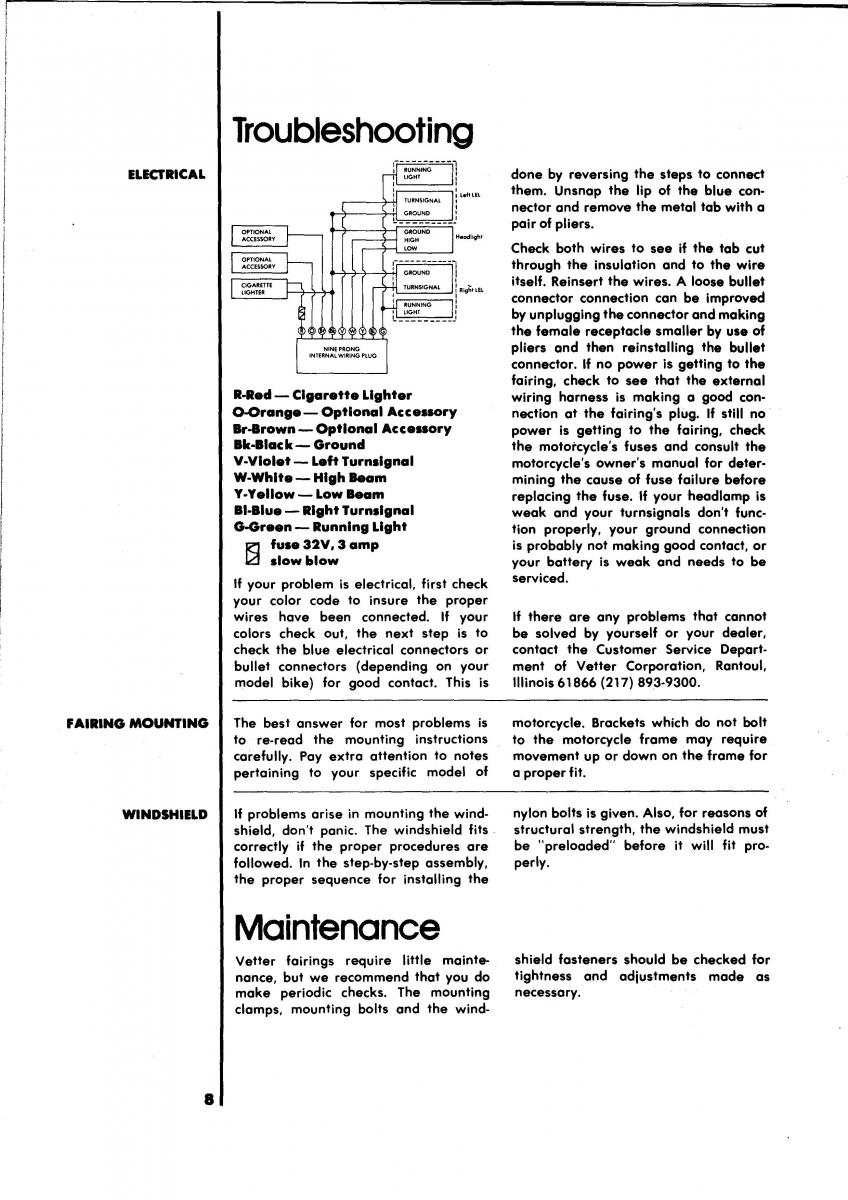
Here is the Vetter wiring diagram:
We have a 1981 Vetter Manual in the gallery:
https://classicgoldwings.com/forum/galle ... m_id=10133
We have a 1981 Vetter Manual in the gallery:
https://classicgoldwings.com/forum/galle ... m_id=10133
OP
OP
saganaga
Well-known member
I checked the connector a few weeks back with a multimeter, and didn't find any battery power going through it. The fairing was on the bike, so I didn't dig deeper.
I did look through the manual and found the same page you did. Once everything is off the bike, I'll take a look at the wiring. Kind of curious where the best place to tap into the battery power, but there is a wire going to the ignition that I'm going to try to hunt down. Else I could run a separate wire to the battery, but that's kind of an ugly hack.
I did look through the manual and found the same page you did. Once everything is off the bike, I'll take a look at the wiring. Kind of curious where the best place to tap into the battery power, but there is a wire going to the ignition that I'm going to try to hunt down. Else I could run a separate wire to the battery, but that's kind of an ugly hack.
- Joined
- Dec 3, 2009
- Messages
- 11,031
- Reaction score
- 299
- Location
- Kingsport, Tennessee
- My Bike Models
- Former '82 GL1100 "The Slug"
Else I could run a separate wire to the battery, but that's kind of an ugly hack.
To have an "always on" condition, you have to run a wire from the battery with it's own fuse. The fuse panel on these bikes is only powered after the key is turned on. However, there is an accessory fuse terminal on the fuse panel for a radio. The + and - of the radio is wired to this terminal. The "always on" leg of the radio power runs to the fuse panel. The Vetter faring wiring uses orange for the radio positive, black for the negative and brown for the radio "always on" terminal. The red wire for the fairing is reserved for a 12 volt outlet usually located as a cigarette lighter outlet on the bottom left side of the fairing. I used mine for charging my phone with a 5 volt USB adapter.


$44.95
Harley-Davidson Bar & Shield Logo Zipper Rugged Graphic Duffel Bag - Black
Wisconsin Harley-Davidson

$74.95
Harley-Davidson 21" Carry-On Rugged Twill Rolling Duffel Bag - Black (22")
Wisconsin Harley-Davidson


$150.00
1984 Honda Gold Wing GL1200 Factory Service Manual Dealer GoldWing Shop Repair Workshop
GLAVIS ENTERPRISES


$80.23
Honda GL 1800 Gold Wing 2001-2010 Repair Manual (Haynes Service & Repair Manual)
Chrome World

$39.95
$59.95
Honda GL1800 Gold Wing 1800 (01-10) Haynes Repair Manual (Paperback)
Haynes Repair Manuals


$102.76
$129.00
Sena Universal Helmet Clamp Kit for CB/Audio of Honda Goldwing (20S, 20S EVO, 30K)
ThrottleCityCycles


$100.00
$169.99
1988 Honda Gold Wing GOLDWING GL1500 Service Shop Repair Manual OEM FACTORY 88
GLAVIS ENTERPRISES

$39.33
$54.95
Clymer Honda GL1200, 1984-1987: Maintenance, Troubleshooting, Repair (Clymer Motorcycle)
Empty Estates


$18.99
2001 2002 2003 2004 2005 Honda GoldWing GL1800/A Service Shop Repair Manual OEM
DD_Liquidators

$44.95
Harley-Davidson Orange Bar & Shield Logo Zip Rugged Graphic Duffel Bag - Black
Wisconsin Harley-Davidson


$39.95
$49.95
Honda GL1500 Gold Wing Motorcycle (1993-2000) Service Repair Manual
Haynes Repair Manuals


$231.99
$287.99
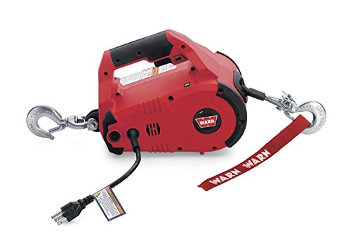
WARN 885000 PullzAll Corded 120V AC Portable Electric Winch with Steel Cable: 1/2 Ton (1,000 Lb) Pulling Capacity , Red
Amazon.com

OP
OP
saganaga
Well-known member
[url=https://classicgoldwings.com/forum/viewtopic.php?p=212631#p212631:3njofnzh said:mcgovern61 » Today, 6:14 am[/url]":3njofnzh]
Else I could run a separate wire to the battery, but that's kind of an ugly hack.
To have an "always on" condition, you have to run a wire from the battery with it's own fuse. The fuse panel on these bikes is only powered after the key is turned on. However, there is an accessory fuse terminal on the fuse panel for a radio. The + and - of the radio is wired to this terminal. The "always on" leg of the radio power runs to the fuse panel. The Vetter faring wiring uses orange for the radio positive, black for the negative and brown for the radio "always on" terminal. The red wire for the fairing is reserved for a 12 volt outlet usually located as a cigarette lighter outlet on the bottom left side of the fairing. I used mine for charging my phone with a 5 volt USB adapter.
I was planning to tap into the red wire that goes to the ignition. That should be always on. I'll add a tiny inline fuse (1A?) to it, to avoid any problems blowing the main fuse.
Speaking of which, while I was on the phone to the Honda dealer, I ordered two more main fuses for a buck each. Figured that's cheap insurance.
OP
OP
saganaga
Well-known member
Dang, one other thing I forgot!
Left side of the engine is pretty oily. Not sure why, but it doesn't seem to be coming from the front engine cover, and the front engine cover, AFAICT, shouldn't have any pressurized oil running though it and the edge of the gasket, that I could see, doesn't appear oily. Could be the left head gasket. Could also be the shifter oil seal. (Guess which one I'm hoping for!)
No noticeable drop in oil level - it's just one of those dirty little oil leaks. I'll have to clean the bike up after the next repair and see what gets dirty first.
I’d bet it’s sifter seal ....fingers crossed
Or a fork seal. I know a guy that tore into an 1800 because of oil coming out of the fairing. Turned out it was getting in the front from a blown fork seal. I had oil all over the bottom of a '77 1000 from a blown seal.
OP
OP
saganaga
Well-known member
I would have preferred that the new gasket would have arrived today, but I did get this in the mail. Sadly, this is the most advanced car radio I will have in a vehicle. Bluetooth and everything, so I should be able to stream music from my phone, after I mess with the A2DP settings on my phone so music goes to the radio.

Also picked up one of these tools for about $15. Some people apparently love them - it's just T handle tool, with each end of the tool accepting a 1/4" socket. It ships with an 8mm, 10mm, and 12mm socket.
.jpg")
Also picked up one of these tools for about $15. Some people apparently love them - it's just T handle tool, with each end of the tool accepting a 1/4" socket. It ships with an 8mm, 10mm, and 12mm socket.
- Joined
- Dec 3, 2009
- Messages
- 11,031
- Reaction score
- 299
- Location
- Kingsport, Tennessee
- My Bike Models
- Former '82 GL1100 "The Slug"
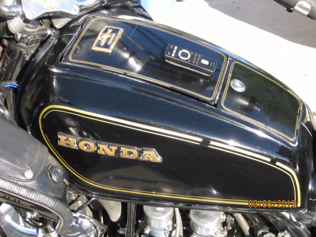
That radio should work great! I see it also has a remote. When I had my Vetter faring, I stuck the remote to the top of the tank lid with velcro tape.
OP
OP
saganaga
Well-known member
[url=https://classicgoldwings.com/forum/viewtopic.php?p=212751#p212751:itiqx1sw said:mcgovern61 » 14 minutes ago[/url]":itiqx1sw]
That radio should work great! I see it also has a remote. When I had my Vetter faring, I stuck the remote to the top of the tank lid with velcro tape.
That's a smart idea!
[url=https://classicgoldwings.com/forum/viewtopic.php?p=212751#p212751:1c0s2ai3 said:mcgovern61 » Thu Sep 12, 2019 9:40 pm[/url]":1c0s2ai3]
That radio should work great! I see it also has a remote. When I had my Vetter faring, I stuck the remote to the top of the tank lid with velcro tape.
Hey that tank looks interesting. The badge at the top of the flap, is it just stuck to the flap, or, is it covering a hole that could be used to accommodate an Aspencade compressor control set?
- Joined
- Dec 3, 2009
- Messages
- 11,031
- Reaction score
- 299
- Location
- Kingsport, Tennessee
- My Bike Models
- Former '82 GL1100 "The Slug"
Hey that tank looks interesting. The badge at the top of the flap, is it just stuck to the flap, or, is it covering a hole that could be used to accommodate an Aspencade compressor control set?
I am assuming you mean the Goldwing Badge at the top of the tank lid?

That is held on by 2 plastic pins and pin nuts. It is a Honda original badge found on Standards.
Yeah, I can see it's off of a Standard because it has the Honda badges on the sides. I had one in '84, but that's too long ago to remember all the details.
I just thought that if that top badge was covering the right size hole it might open up more options for me when buying fake tanks, instead of having to limit myself to Aspencade stuff in order to use the compressor, thanks.
I just thought that if that top badge was covering the right size hole it might open up more options for me when buying fake tanks, instead of having to limit myself to Aspencade stuff in order to use the compressor, thanks.
OP
OP
saganaga
Well-known member
Making progress. Drained the coolant into a clean container to reuse. Took off the water pump cover and spend a good hour removing the old gasket. Pulled the dowel pins, then sprayed the whole area down with water to get rid of any scraps of gasket material.


I really like the OEM Honda gasket. Looks sturdy. Thinking the next time I pull off a front engine cover, I may just stick with the much pricier OEM gaskets.


Reinstalled the cover, torqued everything down, filled up the coolant, and I left a paper towel under the bike to check for leaks overnight.
I really like the OEM Honda gasket. Looks sturdy. Thinking the next time I pull off a front engine cover, I may just stick with the much pricier OEM gaskets.
Reinstalled the cover, torqued everything down, filled up the coolant, and I left a paper towel under the bike to check for leaks overnight.
Well that will definitely fix it, if indeed he problem is at your water pump!
OP
OP
saganaga
Well-known member
Spent 4+ hours installing the radio.
When I had the Vetter fairing off, I checked the wiring on the motorcycle side. An orange accessory wire was from the Vetter connector was never connected to anything. Decided that will become the always-on battery power for the radio.
Disconnected the battery ground first. Then I unplugged the ignition switch, and with a plastic shim I made, I removed the red terminal from the connector.)

I probably should invest in the actual tool to remove terminals from connectors, but the scrap plastic bit worked okay. All that the tool needs to do is to push into the connector and depress a little retaining clip that prevents the terminal from backing out of the connector.
Then I broke open the metal terminal and soldered in a 14 gauge wire, running to an inline glass fuse (1A) and then to the orange Vetter fairing wire.
.jpg")
Ignore the blue plastic tap connector - I didn't install it, and I didn't use it.
I then plugged in the ignition connector, and put the rest of the Vetter wiring back in its bag.

Now, to the Vetter side. Got a question for the old times who were installing car radios in the 1980s. I noticed what looked like two inline fuses for the radio (accessory) power supply. One of the glass fuses look weird - could this be some sort of filter?

Anyways, moving on - had to remove the Vetter sound system box. Which requires removing multiple, annoying screws - it's held in via two plastic screws for the windshield, as well as two metal brackets that attach to other windshield bolts.
After removing the sound system box, and removing the stereo, I ran into more work to do. Old stereo opening looked like this.

For future reference, a dremel with a cutoff wheel doesn't leave a straight, clean cut. I found a handsaw and a rasp was superior for straight lines.
Also, I could not find anything that cleanly and neatly marked the opening I was cutting - ended up using some chalk, but that was less than ideal. But the result was good enough.

Soldered and shrinkwrapped all connectors, as well as a new (battery power) line for the radio on the Vetter side of things. Reassembled the sound box and installed the sound box back on the bike.

This would go a lot faster if I could keep the speakers in the sound box for installation, but I need to remove the speakers to access one screw on each side. At least for most future work, I shouldn't have to remove the sound box at all, since there's now the additional power supply run to the sound box, and the new radio can be removed without opening up the sound box.

Finally, installed the radio.

That was a far bigger job than I thought. Cutting the new opening took time, so did soldering and heat shrinking all the wires. But the result is good.
When I had the Vetter fairing off, I checked the wiring on the motorcycle side. An orange accessory wire was from the Vetter connector was never connected to anything. Decided that will become the always-on battery power for the radio.
Disconnected the battery ground first. Then I unplugged the ignition switch, and with a plastic shim I made, I removed the red terminal from the connector.)
I probably should invest in the actual tool to remove terminals from connectors, but the scrap plastic bit worked okay. All that the tool needs to do is to push into the connector and depress a little retaining clip that prevents the terminal from backing out of the connector.
Then I broke open the metal terminal and soldered in a 14 gauge wire, running to an inline glass fuse (1A) and then to the orange Vetter fairing wire.
Ignore the blue plastic tap connector - I didn't install it, and I didn't use it.
I then plugged in the ignition connector, and put the rest of the Vetter wiring back in its bag.
Now, to the Vetter side. Got a question for the old times who were installing car radios in the 1980s. I noticed what looked like two inline fuses for the radio (accessory) power supply. One of the glass fuses look weird - could this be some sort of filter?
Anyways, moving on - had to remove the Vetter sound system box. Which requires removing multiple, annoying screws - it's held in via two plastic screws for the windshield, as well as two metal brackets that attach to other windshield bolts.
After removing the sound system box, and removing the stereo, I ran into more work to do. Old stereo opening looked like this.
For future reference, a dremel with a cutoff wheel doesn't leave a straight, clean cut. I found a handsaw and a rasp was superior for straight lines.
Also, I could not find anything that cleanly and neatly marked the opening I was cutting - ended up using some chalk, but that was less than ideal. But the result was good enough.
Soldered and shrinkwrapped all connectors, as well as a new (battery power) line for the radio on the Vetter side of things. Reassembled the sound box and installed the sound box back on the bike.
This would go a lot faster if I could keep the speakers in the sound box for installation, but I need to remove the speakers to access one screw on each side. At least for most future work, I shouldn't have to remove the sound box at all, since there's now the additional power supply run to the sound box, and the new radio can be removed without opening up the sound box.
Finally, installed the radio.
That was a far bigger job than I thought. Cutting the new opening took time, so did soldering and heat shrinking all the wires. But the result is good.
Multi tools (like cast saws) are great for cutting plastic. Cheap @ Harbor Frieght.