The work is so much easier when you have the proper tools. Great work Gerry !!
You are using an out of date browser. It may not display this or other websites correctly.
You should upgrade or use an alternative browser.
You should upgrade or use an alternative browser.
Rebuild '82 Standard Wire Harness and Fuse Box
- Thread starter mcgovern61
- Start date


Help Support Classic Goldwings:
This site may earn a commission from merchant affiliate
links, including eBay, Amazon, and others.
OP
OP
- Joined
- Dec 3, 2009
- Messages
- 11,041
- Reaction score
- 308
- Location
- Kingsport, Tennessee
- My Bike Models
- Former '82 GL1100 "The Slug"
WOW! It is hard to believe it has been nearly 1 1/2 years since I last worked on this project. As I am going through the bike preparing for sale next spring, I found the entire harness project still sitting in the box in the back of the garage. It was June 2017 when my Mother-in-Law had to be taken to New York for a major kidney surgery and our lives went on hold from that day forward. Ultimately, she had a minor stroke after surgery, rapidly developed a brain tumor, moved in with us for hospice care and passed last January. During those last few months, I ended up with a torn meniscus and had minor knee surgery myself. It has truly been one thing after another (as many of you have been through too.)
The "Slug" is in the garage. I have been using her when I can. Still less than 600 miles on her this season. I want to finish this project and run the bike with all of the mods before I sell her this spring. It is still fun to work on her. My Wife and I have been purposely distracted together with our boat and she (the boat) is now out of the water. There is a fair amount of work that needs to be done to the boat too, but I really want to get the "Slug" finished.
The "Slug" is in the garage. I have been using her when I can. Still less than 600 miles on her this season. I want to finish this project and run the bike with all of the mods before I sell her this spring. It is still fun to work on her. My Wife and I have been purposely distracted together with our boat and she (the boat) is now out of the water. There is a fair amount of work that needs to be done to the boat too, but I really want to get the "Slug" finished.
Time to get back at it I'd say - enough dogging it!! :music: :music: Seriously, I knew I wanted to do the wiring on my 1200 better than when I started and I have to say that this thread was the impetus for getting going with OEM style connectors, and the cloth wire tape. Will be looking at the wiring on the 1200 during this winter work period to improve it as well. Look forward to reading about your progress and the end result.
Have electrical work to do on my 1500 as well. Get better at this every time it is done.
Cheers
Have electrical work to do on my 1500 as well. Get better at this every time it is done.
Cheers
OP
OP
- Joined
- Dec 3, 2009
- Messages
- 11,041
- Reaction score
- 308
- Location
- Kingsport, Tennessee
- My Bike Models
- Former '82 GL1100 "The Slug"
I have officially "restarted" this project! :Egyptian:
I am still riding the Slug on short trips (no back up vehicle yet plus back pain is still a major issue), but am in the process of accessing all of the parts and pieces in hand to finish this work. 85% of the work has been done and it is really only a matter of adding new ground wires and power wires to the original 82 harness and wrap it up.
I have laid out all of the electrical parts and pieces to check everything again and re-familiarize myself with where I left off. Did a quick test on all of the fuse panel circuits and relays and everything is working as planned. One of the hold ups on the bike itself is pulling and replacing the triple tree with the correct '82 triple tree. The '82 has the mount for the angle sensor for the self cancelling turn signals (which, by the way, is how this whole project started in the first place back in April 2016).
viewtopic.php?p=171895#p171895
 opcorn:
Watching again. Understand the rise of the wiring project, never done, always realize after the fact that should have done it "this way". Cheers


$100.00
$169.99
1988 Honda Gold Wing GOLDWING GL1500 Service Shop Repair Manual OEM FACTORY 88
GLAVIS ENTERPRISES

$55.09
$58.00
WILD HEART Waterproof Motorcycle Duffel Bag PVC500D Double-bottom With Rope Straps and Inner Pocket 40L 66L 100L for Kayaking, Camping, Boating,Motorcycle
ZHONGSHAN WILD FRUIT OUTDOOR


$48.99
$55.00
HONDA GL1000 & GL1100 GOLDWING MOTORCYCLE REPAIR SHOP & SERVICE MANUAL For 1975, 1976, 1977, 1978, 1979, 1980, 1981, 1982, 1983, 1984 & 1985 - NEW, 304 Pages
Classic Automotive Repair Shop & Restoration Manuals

$50.07
M506-2 1993-2000 Honda GL1500 Goldwing Clymer Motorcycle Repair Manual
Classic Automotive Repair Shop & Restoration Manuals


$32.09
$59.95
Honda GL1800 Gold Wing 1800 (01-10) Haynes Repair Manual (Paperback)
Haynes Repair Manuals

$5.33
$6.49
Pink Balaclava Ski Mask Head Mask Full Face Mask Windproof Sun UV Protection Hood for Women Men
Ligart

$35.37
$45.95
Show Chrome Accessories 52-696 Honda Goldwing GL1800 01-10 Radio Panel
Amazon.com

$41.81
$54.95
Clymer Honda GL1200, 1984-1987: Maintenance, Troubleshooting, Repair (Clymer Motorcycle)
Haynes Repair Manuals

$9.95
$14.95
BELL Vortex Hinge Plate Kit Street Motorcycle Helmet Accessories - Black/One Size
Movatik


$76.00
Honda GL 1800 Gold Wing 2001-2010 Repair Manual (Haynes Service & Repair Manual)
Clickgoodwill


$46.95
Harley-Davidson Trailblazer #1 Logo Duffel Bag w/Adjustable Strap - Rust Vintage Large
Wisconsin Harley-Davidson

$150.00
1984 Honda Gold Wing GL1200 Factory Service Manual Dealer GoldWing Shop Repair Workshop
GLAVIS ENTERPRISES


$129.00
Sena 30K / 20S / EVO Helmet Clamp Kit for Honda Goldwing CB Helmet Accessories
ProRidersClub


OP
OP
- Joined
- Dec 3, 2009
- Messages
- 11,041
- Reaction score
- 308
- Location
- Kingsport, Tennessee
- My Bike Models
- Former '82 GL1100 "The Slug"
Your not kidding! :good:[url=https://classicgoldwings.com/forum/viewtopic.php?p=213672#p213672:2r75gnoo said:Rednaxs60 » Thu Oct 10, 2019 10:01 am[/url]":2r75gnoo]
Watching again. Understand the rise of the wiring project, never done, always realize after the fact that should have done it "this way". Cheers
Over the winter and spring, I completely rewired our antique Chris Craft and created a second system. The original system (lights, ignition, generator, starter, bilge pump) is 6 volt DC. I needed to add a 12 volt DC VHF radio and other modern 12 volt items. I did not want to spend the dollars to convert the generator to 12 volt ($300-$400) so I added a 6 volt to 12 volt converter.
The converter runs off a new 6 VDC fuse panel (no fuse or distribution panel in the old 6 volt system). The 6 volt generator produces 10-15 amps at engine speed (constant, no regulator, only brushes). I installed an auxiliary 12 volt AGM battery (same one in my 1100) that powers the 12 volt system. Added new battery shutoff switch, two separate 6 volt batteries and the one 12 volt AGM. ALL NEW WIRE! :shock:
With the new distribution/fuse panels and upgraded wiring, I was able to add a VHF radio, GPS chart plotter, 12 volt bilge pump, 12 volt aux circuit for charging phones, 12 volt spotlight and direct wiring to the horn. The wiring is a huge upgrade from the original cotton covered wiring that was really worn out. Plus, the safety of adding main circuit breakers and cutoff switches meets USCG wiring requirements for carrying passengers for hire.
Example of the original one line diagram:
My new one line diagram:
Original wiring (plus PO work!)
New Fuse panels installed with homeruns for each circuit. These are in process pics. The wires are not secured in place yet.
New 12 volt AGM battery:
Why the work needed to be performed. Hmmm......
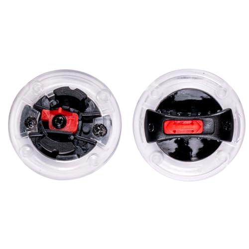
6 volt battery and shutoff switch:
I love marine wiring on older boats. No one industry has a monopoly on the wiring faux pas syndrome.
Have you considered any of the Balmar products for charging multiple batteries, power distribution and such. Used these products on my 30 foot Uniflite and 40 foot Bayliner that we lived on.
Your schematics are very good, mine are still "in the mind stage".
Cheers
Have you considered any of the Balmar products for charging multiple batteries, power distribution and such. Used these products on my 30 foot Uniflite and 40 foot Bayliner that we lived on.
Your schematics are very good, mine are still "in the mind stage".
Cheers
OP
OP
- Joined
- Dec 3, 2009
- Messages
- 11,041
- Reaction score
- 308
- Location
- Kingsport, Tennessee
- My Bike Models
- Former '82 GL1100 "The Slug"
I have not. I have the system setup that the 12 volt AGM receives charge from the 6 volt system which receives it's charge from the 6 volt generator.Have you considered any of the Balmar products for charging multiple batteries, power distribution and such.
The battery selector switch is wired for the two 6 volt banks. When turned off, battery #1 is charged with an AC powered 6 VDC float charger (same one I use to keep the 1100 AGM charged). With the selector switch off, the only power draw is on battery #1 for the 6 volt bilge pump that is automatic and hard wired. When the selector swich is set to both, then both banks receive equal charge from the generator.
Getting a balancer for the 6 volt system is too costly.
OP
OP
- Joined
- Dec 3, 2009
- Messages
- 11,041
- Reaction score
- 308
- Location
- Kingsport, Tennessee
- My Bike Models
- Former '82 GL1100 "The Slug"
One of the procedures I will be changing is the terminal connectors on the buss bars for the new system on the bike. To date, I have been using crimp on spade connectors and dielectric grease. For the boat wiring, I am using crimp connectors that have heat shrink insulators built in. That makes for a much better waterproof connection than using dielectric grease.
Work to date. The buss bar terminals are crimp only:
Connectors with built in heat shrink:
Work to date. The buss bar terminals are crimp only:
Connectors with built in heat shrink:
OP
OP
- Joined
- Dec 3, 2009
- Messages
- 11,041
- Reaction score
- 308
- Location
- Kingsport, Tennessee
- My Bike Models
- Former '82 GL1100 "The Slug"
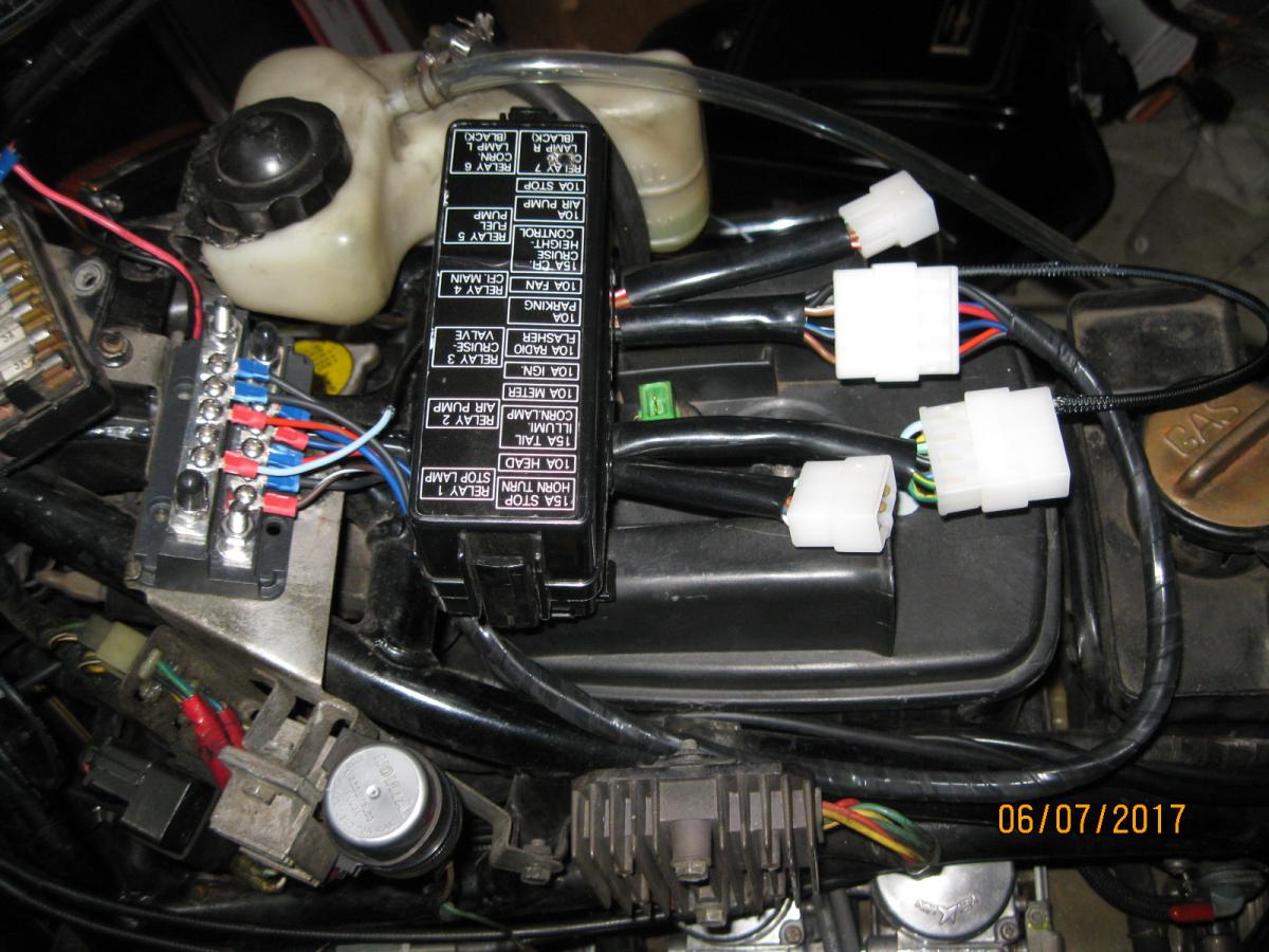
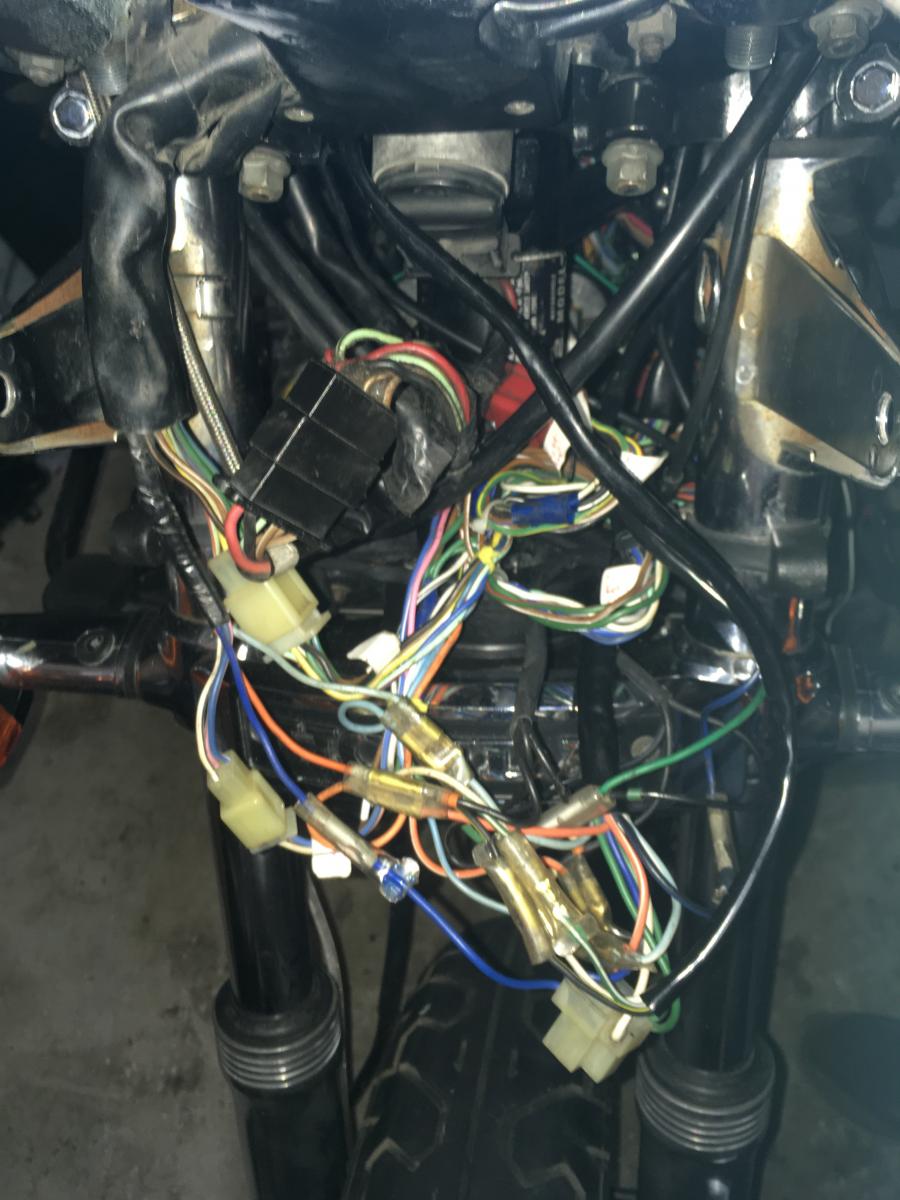
Adding wires to the harness is trickier than I first thought. Not only do you need to use the right gauge, connector and work from a schematic, but routing is also a big issue (where do you start and stop a new wire and how will it exit the harness). It is not only the "exit the harness" issue, but how much space and where does the connector reside? Not much room around the frame to add connectors as you lay the harness back in place. This called for a dry run and mark up to add the balance of the wires:
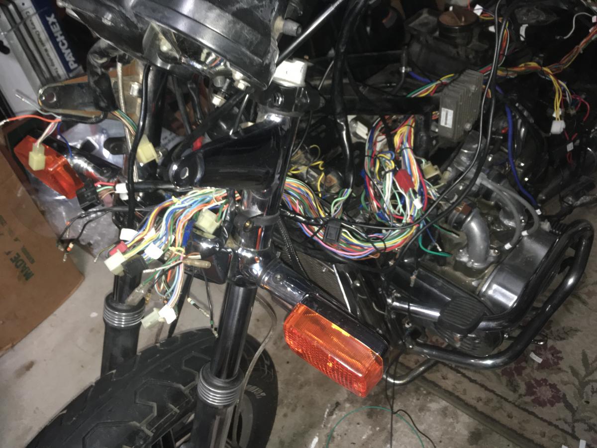
All of these top wires are new and extend the original "fuse box to harness wires" to be able to reach the new fuse/relay panel.
The new wires are allowing the following changes:
*direct connection to ignition coils without sharing load on the same wire as the rest of the 12 volt system per Honda
*new wire to connect fan to fuse panel (1100 fans are not connected to any fuse other than the main 30 amp fuse)
*new wire to connect the new oil pressure switch to a relay to only turn the headlight on when the engine is running
*new wires for the radio installation
*new wire for a combination 12 volt socket and 5 volt USB charger
*new power wire (and 20 amp fuse) to add a second power source from battery to split the harness load
*new wire for trailer power connection
Nice work Gerry
Great update. Just finished up wiring my friends 2010 Triumph Tiger with driving lights, USB-Voltmeter, self cancelling signal light, extra light bar at the back of the bike, new horns and a few other items. Lots of OEM stye connectors used to make for a good install and if wants to, take out the add ons and revert to original.
Someone is going to get a good bike.
Cheers
Someone is going to get a good bike.
Cheers
OP
OP
- Joined
- Dec 3, 2009
- Messages
- 11,041
- Reaction score
- 308
- Location
- Kingsport, Tennessee
- My Bike Models
- Former '82 GL1100 "The Slug"
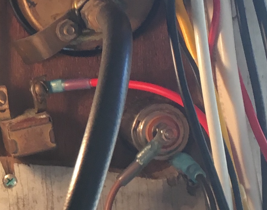
Finishing up the wires. Labeling loose ends is really going to help the next owner track connections after the harness is wrapped and installed.
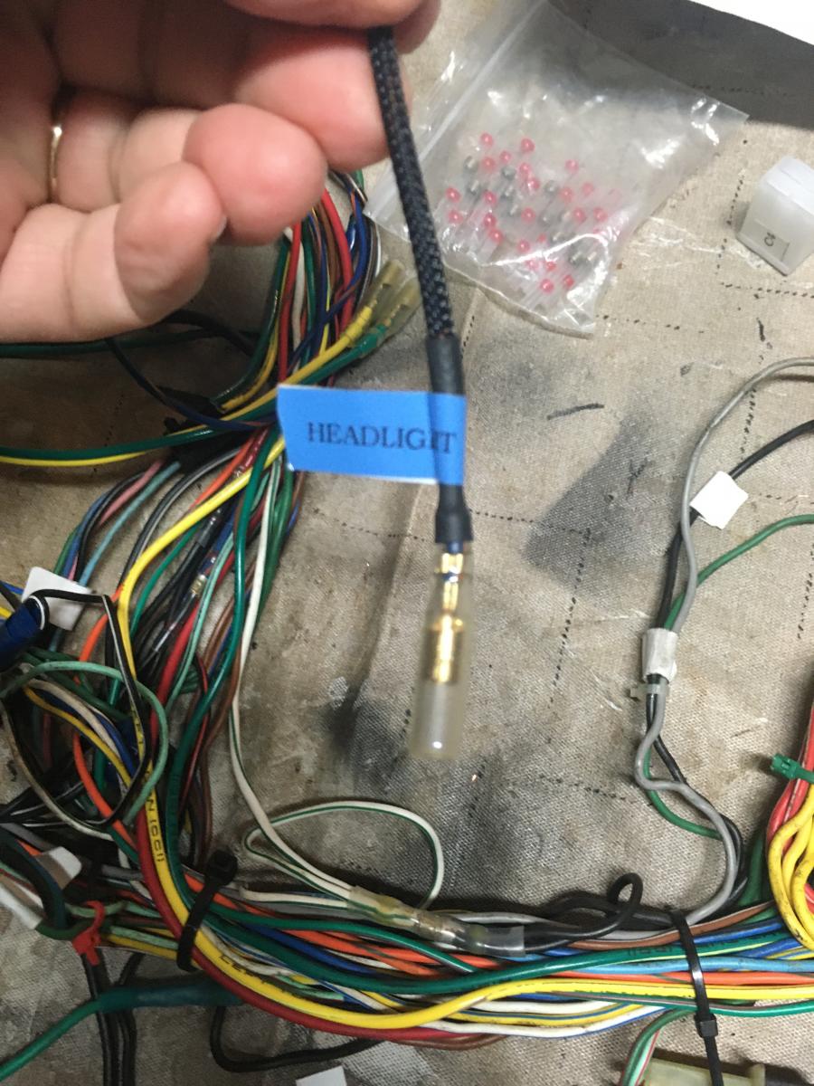
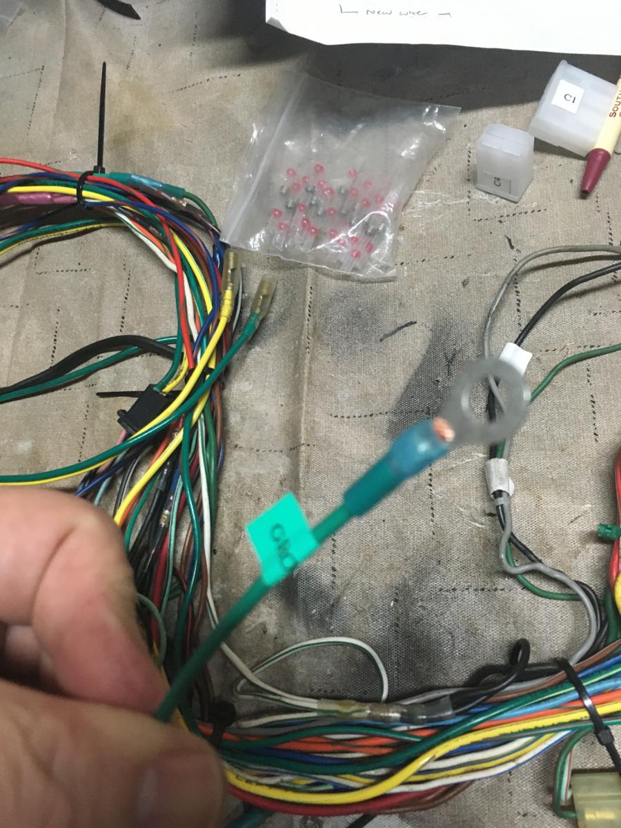
I love these butt connectors. They are heat shrink with solder built right inside the center.
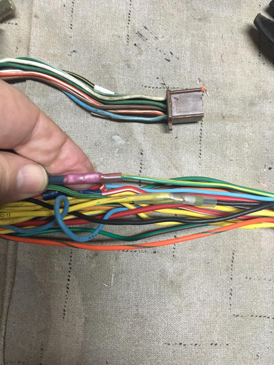
It is amazing how many wires connect inside the headlight bucket! This is a huge step for this old girl. It is the first time since 2007 that her original 1982 wire harness is reconnected and it is the first time since 1995 that it will be live once again.
I love these butt connectors. They are heat shrink with solder built right inside the center.
It is amazing how many wires connect inside the headlight bucket! This is a huge step for this old girl. It is the first time since 2007 that her original 1982 wire harness is reconnected and it is the first time since 1995 that it will be live once again.
OP
OP
- Joined
- Dec 3, 2009
- Messages
- 11,041
- Reaction score
- 308
- Location
- Kingsport, Tennessee
- My Bike Models
- Former '82 GL1100 "The Slug"
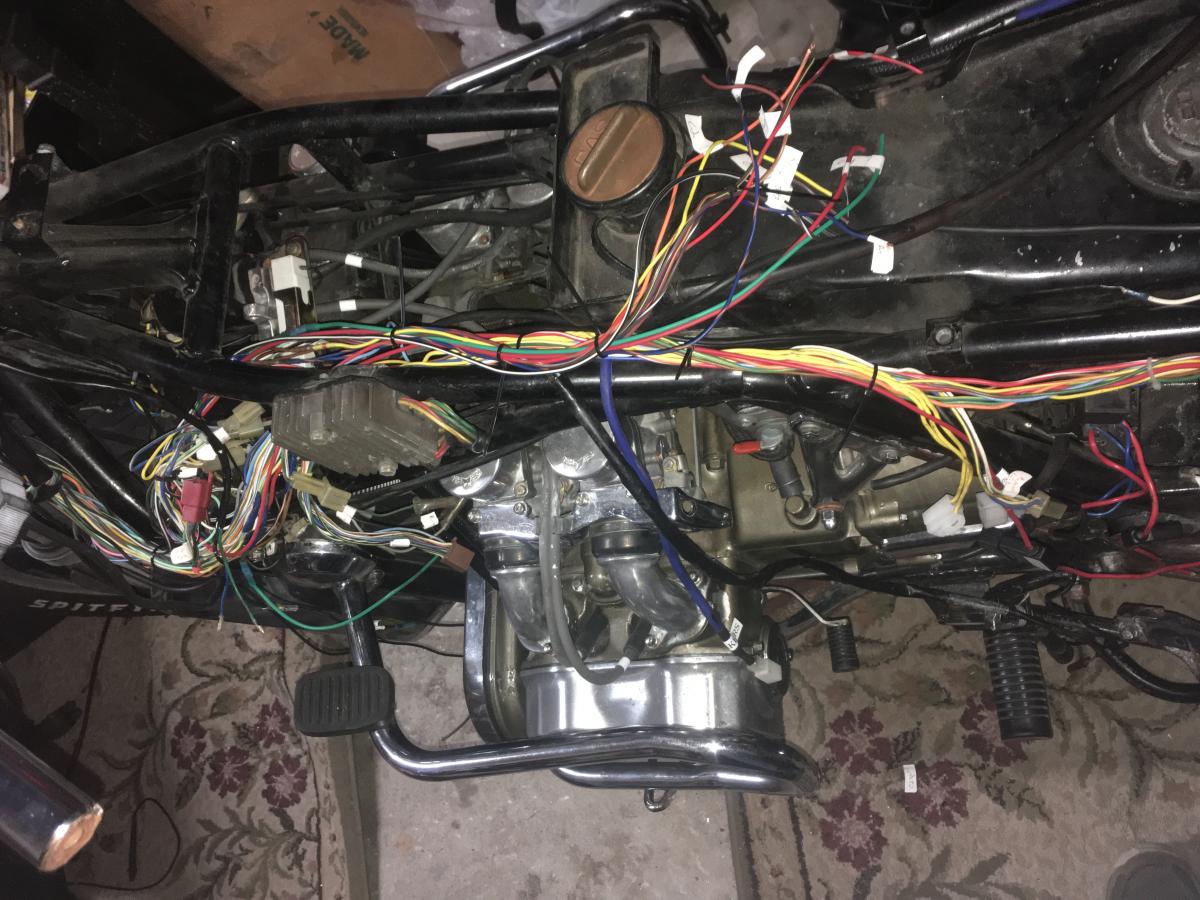
Final routing finished. All connections have been made (except the radio power). I will finish the radio connections later.
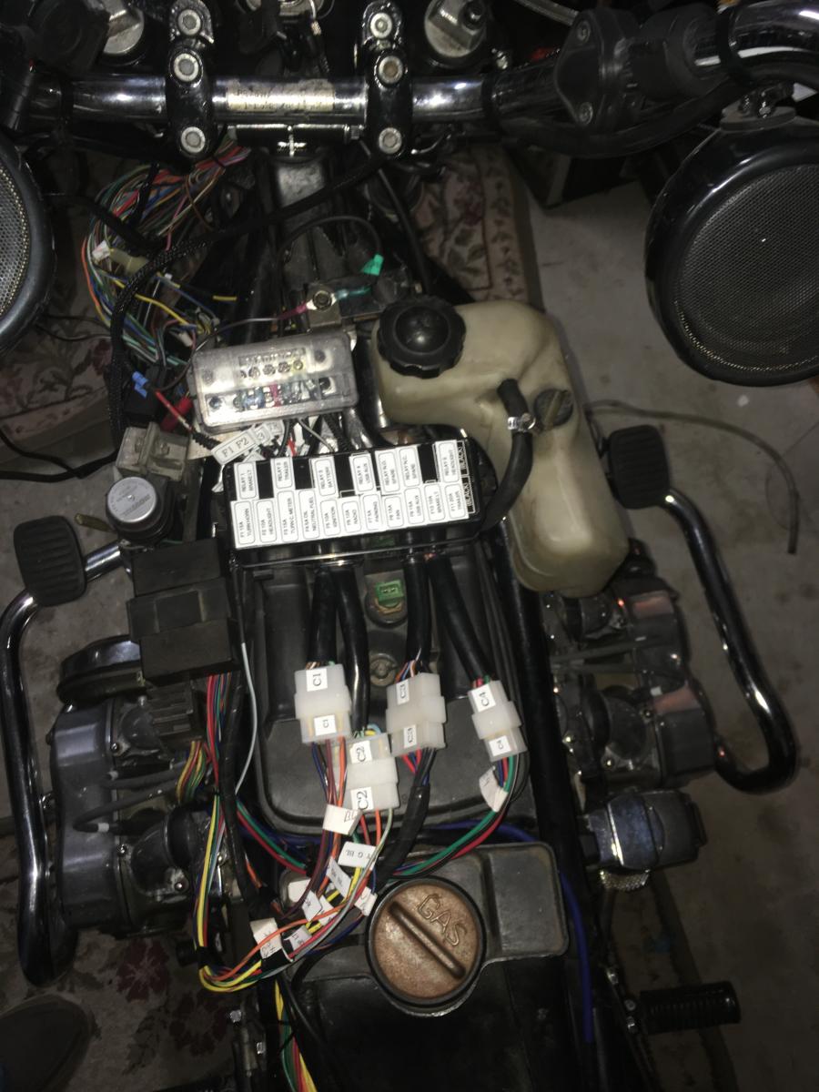
Time to fire up this old girl and test to see if this whole thing was worth the effort.
Time to fire up this old girl and test to see if this whole thing was worth the effort.
OP
OP
- Joined
- Dec 3, 2009
- Messages
- 11,041
- Reaction score
- 308
- Location
- Kingsport, Tennessee
- My Bike Models
- Former '82 GL1100 "The Slug"
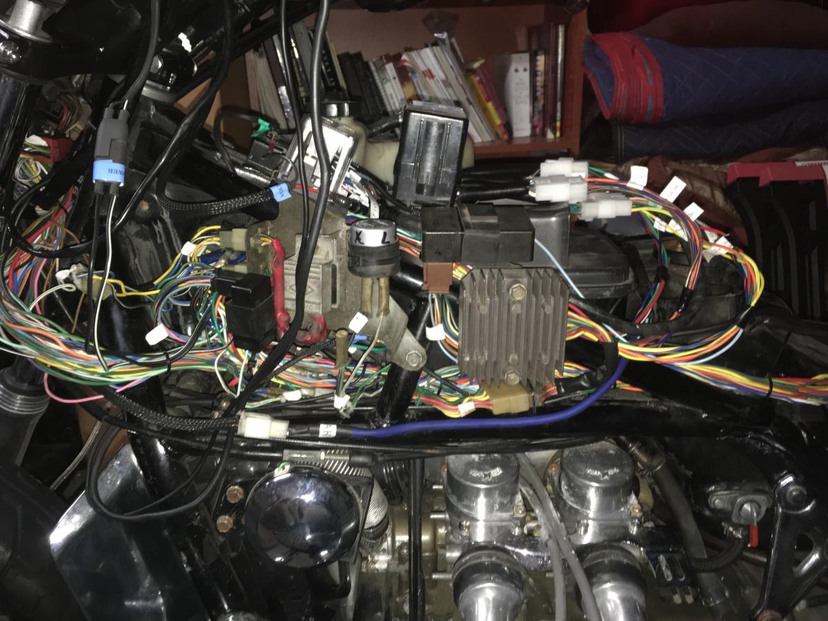
It works!! :yahoo: :Egyptian: :heat:
Fired her up and everything works! The new headlight rely works like a champ. Brake light relay makes the brake lights much brighter. Actually, all of the lights are brighter. The headlight seems like it really gained some candlepower.
There are two buss bars in the terminal strips. One receives power from the original 14 gauge power wire that travels from the battery connection through the key switch and then back into the harness. The other one is connected via a relay that triggers a direct wire from the battery (with a new 20 amp fuse). The battery is measuring 15.3 volts with the engine running at 2000 RPM (charging rate). The main wire at the terminal is measuring 13.4 volts at the buss (quite a loss), but the new wire from the battery is measuring 15.2 volts and that is the wire that is powering the coils, lights and new relays.
This just shows you how much voltage loss there is in the original wiring. Here is a video of the headlight relay in action. The bike has only been running for a minute:
https://www.youtube.com/watch?v=BA2saquEKdw
:clapping: k:
k:
OP
OP
- Joined
- Dec 3, 2009
- Messages
- 11,041
- Reaction score
- 308
- Location
- Kingsport, Tennessee
- My Bike Models
- Former '82 GL1100 "The Slug"
Time to make the last connections for the radio. Next step is pull the harness off and wrap her up! :builder:
Denver
Well-known member
mcgovern61 wrote;
Sort of like the brain, connected to everything, or it just doesn't work.
It is amazing how many wires connect inside the headlight bucket!
Sort of like the brain, connected to everything, or it just doesn't work.
- Joined
- Dec 3, 2009
- Messages
- 22,463
- Reaction score
- 275
- Location
- Van Nuys Ca.
- My Bike Models
- 1983 Interstate
2018 KLR 650
2018 BMW S1000 RR
- My Bike Logs forum link
- https://classicgoldwings.com/forums/dan-filipi.122/
Wow the labels are great!